3 day emergency delivery
How Do Absolute Encoders Work?
SSI Interface
For machines where several axes have to be automated (e.g. robots), the cabling of rotary encoders with bit-parallel interface can become a problem, especially when high resolutions are necessary.
A solution for this problem is the synchronous-serial-interface (RS 485/RS 422). The synchronous-serial-interface (SSI) enables a data transmission with only one 6 wire cable.
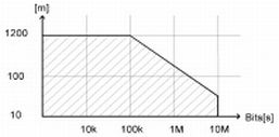
Drivers that meet the RS 485 standard allow transmission rates up to 10 Mbps/s and line lengths up to 1200 m. This is entirely sufficient for most applications. The maximum transmission rate is dependent on the transmission length.
Only one twisted pair line for the data and one twisted pair line for the clock are necessary. The power supply of the rotary encoders needs only two wires, the same as a bit-parallel interface.
The balanced transmission provides a high noise immunity; crosstalk on the line does not effect the signals. The twisted pair lines are sufficient for the transmission. But extremely high noise immunity is achieved when shielded twisted pair lines are used.

and transmission rate
Transmission
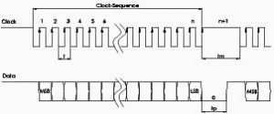
The position value is transmitted synchronously to the clock signal of the control system, starting with the most significant bit (MSB).
When non-operational, the clock as well as the data line is high. As soon as the clock signal of a clock sequence changes for the first time from low (L) to high (H), the bit-parallel data on the parallel-serial-converter will be stored via an internal SLoad-Signal in the input latch of the shift register. This ensures that the data cannot change during the transmission of a position value. With the following rising edge transition of the clock signal, the transmission begins with the most significant bit (MSB).
When non-operational, the clock as well as the data line is high. As soon as the clock signal of a clock sequence changes for the first time from low (L) to high (H), the bit-parallel data on the parallel-serial-converter will be stored via an internal SLoad-Signal in the input latch of the shift register. This ensures that the data cannot change during the transmission of a position value. With the following rising edge transition of the clock signal, the transmission begins with the most significant bit (MSB).
With each following rising edge transition of the clock signal, the next lower significant bit is set on the output of the data line. After the least significant bit is shifted out, the last rising edge transition of the clock signal switches the data line to low (transmission end).
After the last falling edge of the clock signal, a retriggerable mono-flop determines with its internal delay time tm, how long it will take until the rotary encoder or another encoder can be selected for the next transmission. With this, the minimal admissible break time between two successive clock sequences is determined.
There is a differentiation between single transmission and multi transmission of a position value.
To transmit the position value, a determined number n of clock impulses has to be placed on the clock entry of the encoder.
For the single transmission number is n = 13 for the single turn model and n = 25 for the multi turn model.

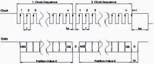
A multiple transmission of a position value is possible with doubling or multiplying the clock sequence. It is very important that a clock sequence includes n + 1 = 26 clocks for multi turn and n + 1 = 14 clocks for single turn.
After the last Low-to-High transition of a 26-clock sequence, a “L” signal appears on data output. The double (or multiple) successive position values are separated from another with this information.

